
VDWall LVP605 Series LED HD Video Processor
3× Video · S-Video · YPbPr · 2× VGA · HDMI · DVI in · VGA + 2× DVI out · cascade to 4032×2112
A 1U rack-mount LED video processor that takes three composite video inputs, S-Video, YPbPr, two VGA (RGBHV), HDMI and DVI, scales them to one VGA and two DVI outputs, and grows past its 2304×1152 single-unit ceiling by running units in parallel — supplied factory-direct by Excelled, an LED display manufacturer and controller supplier for global B2B system integrators.

VDWall LVP605 LED HD Video Processor at a Glance
What is it? The LVP605 series is VDWall’s LED HD video processor — a 1U 19-inch rack unit that scales and switches video sources before the LED wall. The vendor’s own documentation titles it “LVP605 series LED HD Video Processor” and the silkscreen on the unit reads LVP605S; the series covers the LVP605D, LVP605S and LVP605 variants.
What can it take in? Three Video (composite) inputs, one S-Video, one YPbPr, two VGA (RGBHV), one HDMI, one DVI and an extended (optional) port — with PC formats up to 2048×1152_60Hz on VGA, 2304×1152_60Hz on DVI, 1920×1080p_60Hz on HDMI, and PAL/NTSC video on the composite and S-Video paths.
How does it reach the LED wall? Through its 1× VGA and 2× DVI outputs and the on-board sending card slots (cards optional): fit a sending card and the processor drives the receiving cards directly, or hand off to an external sending card over DVI and let that card feed the wall.
Who is it for? Rental and staging companies, TV studio centers, theaters, high-end meeting rooms and exhibition builds — anywhere a proven, familiar front-end is worth more than an exotic one.
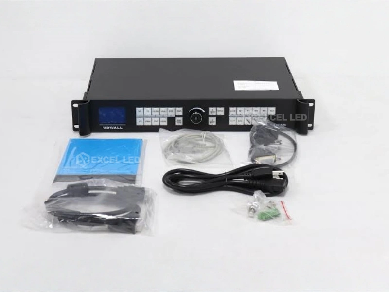
What is included? Standard accessories are a 1.5 m power cord, a 1.5 m DVI cable, a 0.5 m DVI cable, a 1.5 m RS232-RJ45 cable and a 0.2 m net cable. Configuration and pricing come from our sales team — send the source list and wall size and we quote the chain.
Why the VDWall LVP605 Is Still a Default Front-End in the LED Industry
The LVP605 is one of VDWall’s longest-running and most widely deployed LED video processors — a model the LED industry knows well. That is positioning, not marketing: a processor whose connectors, menus and wiring are already familiar to the technicians who will install it is a processor that commissions faster and argues less on site.
The architecture explains the longevity. Everything a wall needs fits in 1U: three composite Video inputs, S-Video, YPbPr, two VGA (RGBHV), HDMI and DVI on the input side; one VGA and two DVI on the output side; a documented parallel-cascade path past the 2304×1152 single-unit ceiling; documented hot spare pairs to hold a backup source; and sending card slots so the wall-side hardware can live inside the same chassis.
Nothing here is exotic — standard BNC, 15-pin D_Sub, 4-pin mini DIN and DVI connectors, PAL/NTSC video systems, 1V(p_p)/75Ω composite levels. That is exactly why it stays in racks. How that chain is wired end to end is covered in our LED control system guide.
Rack-Ready Chassis
482.6 × 274 × 66.6 mm in a 1U 19-inch form factor, 3.2 kg net — one rack slot for the whole front-end.
PIP / POP and Text
Picture-in-picture, picture-on-picture and text overlay are documented front-panel functions, not software extras.
Hot Spare Pairs
Documented failover pairs — HDMI→DVI, V1→V3, V2→S-Video, VGA1→VGA2 — keep a backup source standing by.
Parallel Cascading
Screens wider than 2304×1152 are driven by units in parallel with no misalignment or delay between them.
LVP605 Inputs and Outputs: Video, S-Video, YPbPr, VGA, HDMI and DVI
The input set is broad rather than trendy, and that is the point. Legacy composite and S-Video feeds from cameras, players and switchers sit alongside YPbPr (SD/HD), two independent VGA (RGBHV) channels, HDMI with HDCP and a DVI input — so the processor takes both the old rack of sources and the new laptop without a conversion box in between. Video runs PAL/NTSC at 1V(p_p)/75Ω composite; S-Video splits into Y at 1.0V(p_p)/75Ω and C at 0.35V(p_p)/75Ω; VGA carries R, G, B at 0.7V(p_p)/75Ω.
On the digital side, the ceiling is stated plainly in the manual: VGA to 2048×1152_60Hz, DVI to 2304×1152_60Hz under VESA, and HDMI to 2304×1152_60Hz under VESA or 1920×1080p_60Hz under CEA-861 / HDMI 1.3 with HDCP. YPbPr accepts SD and HD under CEA-861 to 1920×1080P_60Hz. Not sure which input suits which venue source? Our LED video processor guide walks through the decision, and the LED video splicer guide covers the wider-canvas case.
| Input / Output | Connector | Format and level |
|---|---|---|
| Video ×3 | BNC | PAL/NTSC; 1V(p_p)/75Ω composite. |
| S-Video ×1 | 4-pin mini DIN (female) | PAL/NTSC; Y 1.0V(p_p)/75Ω, C 0.35V(p_p)/75Ω. |
| YPbPr ×1 | BNC ×3 | SD/HD (CEA-861) ≤1920×1080P_60Hz; Y=1.0V(p_p)/75Ω, Pb=0.35V(p_p)/75Ω, Pr=0.35V(p_p)/75Ω. |
| VGA ×2 | 15-pin D_Sub (female) | PC (VESA) ≤2048×1152_60Hz; R, G, B = 0.7V(p_p)/75Ω. |
| HDMI ×1 | HDMI | HDCP; PC (VESA) ≤2304×1152_60Hz; HDMI 1.3 (CEA-861) ≤1920×1080p_60Hz. |
| DVI ×1 | 24+1 DVI_D | PC (VESA) ≤2304×1152_60Hz. |
| EXT (Extended) | Optional port | Extended input, optional. SDI-class formats documented for the series: SMPTE 259M-C, SMPTE 292M, SMPTE 274M/296M and SMPTE 424M/425M — 480i_60Hz, 576i_50Hz, 720p, 1080i, 1080p, on BNC. |
| VGA OUT ×1 | 15-pin D_Sub (female) | RGBHV, using the output format set below — VESA tables per VESA. |
| DVI OUT1 ×1 | 24+5 DVI_I | Same output format set as VGA OUT. |
| DVI OUT2 ×1 | 24+1 DVI_D | Same output format set as VGA OUT. |
| Audio | External audio in / out | 2.0Vp-p / 10KΩ. |
The output stage itself carries a fixed VESA set plus a custom mode for LED canvases that match no monitor on earth. Standard outputs cover 1024×768_60/75Hz, 1280×1024_60/75Hz, 1600×1200_60Hz, 1920×1080p_50/60Hz, 1366×768_60Hz, 1440×900_60Hz, 2048×1152_60Hz, 2560×816_60Hz, 2304×1152_60Hz, 1920×1200_60Hz and the portrait and square LED shapes 1200×1600_60Hz, 1080×1920_60Hz and 1536×1536_60Hz. Custom output allows a user-defined format with a maximum horizontal pixel of 3840 or a maximum vertical pixel of 1920, and a total pixel count of no more than 2.65 million at 60Hz — which covers ultra-wide banner walls, portrait columns and non-standard cabinet arithmetic without forcing the wall to be re-specced around the processor.


Wiring the LVP605 to an LED Wall: Step by Step
The LVP605 sits in front of the wall-side hardware, exactly where a processor belongs. Two paths are documented: fit an optional sending card into the chassis slots and drive the receiving cards from the processor itself, or take DVI OUT1 / DVI OUT2 into an external sending card and let that card distribute to the wall. Either way, the processor decides what the wall sees.
- Rack and power the unit. Mount the 1U chassis (482.6 × 274 × 66.6 mm) in a standard 19-inch rack and connect 100–240VAC 50/60Hz to the AC power jack — maximum consumption is ≤20W.
- Patch the sources. Cameras and players on the three Video BNC inputs, S-Video and YPbPr; laptops on the two VGA (RGBHV) channels, HDMI or DVI. Use the extended (optional) port for the additional input path your build requires.
- Choose the wall-side path. Insert an optional sending card in the slots so the unit feeds the receiving cards directly, or run DVI OUT1 / DVI OUT2 to an external sending card — the DVI loop is documented for downstream devices.
- Select the input. Use the front-panel input signal select keys or the control software to lock onto the source, and let VGA auto align analogue computer signals.
- Set the output format. Pick a standard output format or build a custom canvas within the 3840 / 1920 / 2.65-million-pixel rules, then confirm it in output image settings.
- Configure audio and hot spare. Route the external audio input and output, then set the documented hot spare pairs (HDMI→DVI, V1→V3, V2→S-Video, VGA1→VGA2) so a dropped feed has a backup.
- Save the setup. Store the configuration, set the Device ID when several units are addressed from one PC, and run the test pattern before doors open.
If this is your first processor install, the sequence in how to connect an LED controller maps to the same chain. The wall side of the handoff is hardware in its own right — see the Mooncell MTB2000E sending controller for a typical sending card pairing.

Cascading LVP605 Units for Screens Beyond 2304×1152
A single LVP605 drives a maximum output resolution of 2304×1152. Bigger walls are not a dead end — they are a parallel job. VDWall documents screens larger than that single-unit ceiling being driven by several units connected in parallel, with no misalignment or delay between them, which is what makes the approach usable on live content rather than only on static media.
The manual gives two worked examples. In the first, five LVP605 units drive a 4032×2112 LED screen: four run in parallel and one acts as the master, controlling and switching the input signals for the group. In the second, two units in parallel display two or three different pictures on a 1792×672 screen, and up to 19 input signals can be connected across the two units in parallel — enough source count that the processor group, not the wall, becomes the natural switching point.
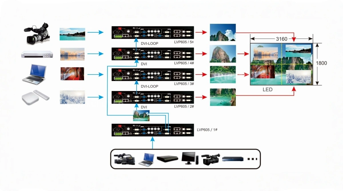
The SDI families named in the manufacturer’s input tables come from the SMPTE standards published for broadcast video. Plan the canvas arithmetic before you order: the pixel budget per unit (custom formats capped at 3840 horizontal or 1920 vertical, 2.65 million pixels total at 60Hz) decides how many units a wall needs. Our team runs that split with you, and the receiving side is the same family used with MRV208 receiving cards.
LVP605 User Manual, Control Software and Documentation
Day-to-day operation happens on the front panel: an LCD screen with input signal select, parameter setup, PIP/POP and text overlay controls, and VGA auto for analogue sources. When the show grows past what buttons can hold, the RS232 control ports and a Windows application take over, with Device ID addressing so one PC can command several processors in a cascade.
The Documented PC Control Program
The manual names the program “LVP605 Control Software.exe” and documents its setting groups: language selection, output image settings, text overlay, brightness / saturation / sharpness, audio configuration, hot spare, test pattern and factory settings, plus PIP/PBP settings with four custom modes (M1–M4) and mosaic settings for split-screen looks. RS232 is the physical control path underneath it, and Device ID addressing is what keeps a multi-unit rack addressable from one machine. Factory settings give you a known-good starting point when a venue’s source behaves oddly two hours before doors.

Seamless Switching, Fade-In / Fade-Out and Blending
The switching engine is what separates a processor from a switch box. VDWall documents the LVP605 as able to realize seamless switching and fade-in / fade-out between, or blending of, any two signals in different channels — with the honest caveat that there is a short moment of blank screen when switching signals in the same channel. The effect is chosen from the panel’s effect selector (C / F): seamless switching (CUT), fade-in / fade-out with a time settable to 0.5S, 1S or 1.5S, or blending.
One documented exception to plan around: YPbPr does not take part in seamless switching or fade-in / fade-out, so switching any signal to YPbPr shows a short blank moment. That is a limitation of the design rather than a defect, and it matters on any show with a component source in the running order — route it into the preset chain, or cover the transition.
The control software lists the same capability set: seamless switching or fade-in / fade-out of input signals, 4 customizable PIP / PBP display modes and text overlay, and switching on / off of bypass, freeze and mosaic. Bypass is documented as the PC signal pass-through, switching between part and full display of the PC signal.

How to Get the LVP605 Manual and Datasheet
The document to ask for is the vendor’s VDWall “LVP605 Series User Manual” — Chapter 6 is its Specifications chapter, and it is the source of every figure on this page. Excelled supplies the current revision with every unit and on request: tell us which variant you run (LVP605D, LVP605S or LVP605) and what you are building, and we return the manual PDF, the datasheet and a configuration note for your wall. We do not publish a fixed download link for it, because vendor documents are revised without notice and a stale PDF causes more problems than it solves; the copy we send is matched to your unit and your firmware.
LVP605 vs LVP615S vs LVP909: Which VDWall Processor?
Three VDWall processors, three different jobs. The table compares only manufacturer-published data; a dash means the item is not stated in the data used for this comparison.
| Model | LVP605 ☆ | LVP615S | LVP909 |
|---|---|---|---|
| Role | Long-running LED HD processor, 1U rack | Processor with DisplayPort and SDI loop | Multi-output splicing processor |
| Video inputs | 3× Video, 1× S-Video, 1× YPbPr | 2× Video, 1× YPbPr | 2× Video |
| PC & digital inputs | 2× VGA, 1× HDMI, 1× DVI, EXT (optional) | 2× VGA, 1× DP, 1× DVI, 1× HDMI | 1× VGA, 1× HDMI, 1× DVI |
| SDI | SDI-class formats documented for the series (SMPTE 259M-C / 292M / 274M / 296M / 424M / 425M) | 1× SDI in + SDI loop | 1× SDI (SDI / HD-SDI / 3G-SDI) |
| Outputs | 1× VGA + 2× DVI | 1× VGA + 2× DVI | 1× VGA + 4× DVI |
| Output ceiling | Standard to 2304×1152_60Hz; custom max 3840 horizontal or 1920 vertical, ≤2.65 MP @60Hz | Custom output width ≤3840, height ≤1920 | Each output max 1920×1200@60Hz or 1440×1440@60Hz |
| Large-canvas path | Parallel cascade: single unit 2304×1152, e.g. 5 units → 4032×2112 | — | Single unit max 14400 px horizontal or 6400 px vertical; 2/3/4-channel splicing |
| Power | ≤20W | ≤25W | ≤45W |
| Typical fit | Mixed legacy and digital sources, cascade builds | Jobs needing DisplayPort plus an SDI loop | Wide walls with 4 outputs and channel splicing |
Model pages: VDWall LVP615S LED HD video processor · VDWall LVP909 LED video wall processor · VDWall LVP100 compact LED video processor. Send the source list and wall size and our engineers map the chain in one reply.
VDWall LVP605 Technical Specifications
Every figure below is taken from the manufacturer’s LVP605 series documentation, specifications chapter. Nothing is estimated.
| Parameter | Specification |
|---|---|
| Product type | LED HD video processor (VDWall LVP605 series: LVP605D / LVP605S / LVP605) |
| Inputs | 3× Video; 1× S-Video; 1× YPbPr; 2× VGA (RGBHV); 1× HDMI; 1× DVI; 1× EXT (Extended, optional port) |
| Input connectors | VGA 15-pin D_Sub (female); DVI 24+1 DVI_D; YPbPr BNC×3; Video BNC; S-Video 4-pin mini DIN (female); SDI BNC |
| Video system | PAL / NTSC |
| Composite video level | 1V(p_p) / 75Ω |
| S-Video level | Y 1.0V(p_p) / 75Ω; C 0.35V(p_p) / 75Ω |
| YPbPr format | SD/HD (CEA-861) ≤1920×1080P_60Hz; Y = 1.0V(p_p)/75Ω, Pb = 0.35V(p_p)/75Ω, Pr = 0.35V(p_p)/75Ω |
| VGA input format | PC (VESA) ≤2048×1152_60Hz; R, G, B = 0.7V(p_p)/75Ω |
| DVI input format | PC (VESA) ≤2304×1152_60Hz |
| HDMI input format | HDCP; PC (VESA) ≤2304×1152_60Hz; HDMI 1.3 (CEA-861) ≤1920×1080p_60Hz |
| SDI / HD-SDI / 3G-SDI format | SMPTE 259M-C, SMPTE 292M, SMPTE 274M/296M, SMPTE 424M/425M — 480i_60Hz, 576i_50Hz, 720p, 1080i, 1080p |
| Audio | 2.0Vp-p / 10KΩ (external audio input and output ports) |
| Outputs | 1× VGA (RGBHV); 2× DVI |
| Output connectors | VGA OUT 15-pin D_Sub (female); DVI OUT1 24+5 DVI_I; DVI OUT2 24+1 DVI_D |
| Output VGA / DVI formats | 1024×768_60/75Hz; 1280×1024_60/75Hz; 1600×1200_60Hz; 1920×1080p_50/60Hz; 1366×768_60Hz; 1440×900_60Hz; 2048×1152_60Hz; 2560×816_60Hz; 2304×1152_60Hz; 1920×1200_60Hz; 1200×1600_60Hz; 1080×1920_60Hz; 1536×1536_60Hz |
| Customizable output format | Maximum horizontal pixel 3840 OR maximum vertical pixel 1920; total pixels ≤2.65 million @60Hz |
| Single-unit output ceiling | 2304×1152 maximum output resolution; larger screens are driven by units connected in parallel with no misalignment or delay |
| Cascade examples (documented) | 5 units — 4 in parallel plus 1 master controlling and switching inputs — driving a 4032×2112 LED screen; 2 units in parallel showing 2 or 3 different pictures on a 1792×672 screen, with maximally 19 input signals connectable to 2 units in parallel |
| Control | Front panel buttons; RS232 control ports; Windows control software (“LVP605 Control Software.exe”) with Device ID addressing |
| Documented panel functions | LCD screen; input signal select; parameter setup; PIP/POP and text overlay; VGA auto; AC power jack and switch; extended input port (optional); DVI loop; sending card slots (cards optional); external audio input and output ports; RS232 control ports |
| Software settings | Language selection; output image settings; text overlay; brightness / saturation / sharpness; audio configuration; hot spare; test pattern; factory settings; PIP/PBP settings with 4 custom modes M1–M4; mosaic settings |
| Hot spare pairs | HDMI→DVI; V1→V3; V2→S-Video; VGA1→VGA2 |
| Switching effects | Seamless switching (CUT); fade-in / fade-out with a time settable to 0.5S, 1S or 1.5S; blending — seamless switching and fade-in / fade-out between, or blending of, any two signals in different channels. A short moment of blank screen occurs when switching signals in the same channel |
| Switching limitation | YPbPr does not take part in seamless switching or fade-in / fade-out — a short moment of blank screen appears when any signal is switched to YPbPr |
| Bypass, freeze and mosaic | PC signal bypass output, switching between part and full display of the PC signal; bypass, freeze and mosaic switched on / off from the control software |
| Input voltage | 100–240VAC 50/60Hz; maximum power consumption ≤20W |
| Environment | Temperature 5–40°C; humidity 15–85% |
| Product size | 482.6mm (L) × 274mm (W) × 66.6mm (H) — 1U 19-inch rack; package size 535×370×145mm |
| Weight | G.W. 5.0 kg / N.W. 3.2 kg |
| Standard accessories | Power cord 1.5m; DVI cable 1.5m; DVI cable 0.5m; RS232-RJ45 1.5m; net cable 0.2m |
| Documented applications | Rental; staging; TV studio center; theater; high-end meetings; exhibition |
LVP605 Buying Guide: 5 Checks Before You Order
- Count sources by connector, not by name. Three Video BNC, S-Video, YPbPr, two VGA, HDMI and DVI are standard. If the job also needs DisplayPort or a dedicated SDI loop, the LVP615S is the closer match; if it needs four outputs and channel splicing, look at the LVP909.
- Do the canvas maths first. A single unit outputs up to 2304×1152, and custom formats are capped at 3840 horizontal or 1920 vertical within a 2.65-million-pixel budget at 60Hz. Anything larger becomes a parallel cascade — decide the unit count before the quote, not after.
- Decide the wall-side path. Sending card slots are built in but the cards are optional. If your standard is an external sending card, confirm DVI OUT1 / DVI OUT2 into that card; if you want one chassis to do both, spec the card with the processor.
- Plan control and addressing. The Windows control software uses Device ID addressing — important on cascade builds where one laptop must reach several units over RS232. Map IDs during commissioning, not on show day.
- Match the environment to the rating. 5–40°C and 15–85% humidity is a wide but finite window; outdoor or unheated installs need conditioned racks, and the ≤20W draw makes that easy to plan.
Price and Cost Factors
LVP605 pricing follows the configuration: the processor itself, whether an optional sending card is fitted in the chassis slots, the extended input option, the accessories you need beyond the standard set, and quantity. Send our team the source list, wall pixel dimensions and the wall-side card model, and we quote the complete processing chain.
Cross-brand alternatives worth pricing alongside: the Huidu HD-VP210 LED video processor for compact installs.
VDWall LVP605 LED Video Processor FAQ
Q1 What is the VDWall LVP605 LED video processor?
The LVP605 series is VDWall’s LED HD video processor — a 1U 19-inch rack unit that accepts video, computer and digital sources, scales and switches them, and outputs to the LED wall through one VGA and two DVI ports or through optional sending cards fitted in its own chassis slots. The series covers the LVP605D, LVP605S and LVP605 variants; the silkscreen on the unit reads LVP605S.
Q2 How does the LVP605 connect to an LED screen?
Two documented paths. Either fit an optional sending card into the processor’s sending card slots and drive the receiving cards from the unit, or take DVI OUT1 / DVI OUT2 into an external sending card and let that card feed the wall. A DVI loop is documented for downstream devices, and the rear panel also carries RS232 control ports.
Q3 What inputs does the LVP605 accept?
Three Video (composite, BNC), one S-Video, one YPbPr, two VGA (RGBHV) on 15-pin D_Sub, one HDMI, one DVI, and an extended (optional) port. Video runs PAL/NTSC at 1V(p_p)/75Ω; S-Video carries Y at 1.0V(p_p)/75Ω and C at 0.35V(p_p)/75Ω; VGA carries R, G, B at 0.7V(p_p)/75Ω.
Q4 Does the LVP605 support seamless switching, fade-in and blending?
Yes, with one documented exception. The LVP605 can realize seamless switching and fade-in / fade-out between, or blending of, any two signals in different channels, chosen from the effect control as seamless switching (CUT), fade-in / fade-out with a time settable to 0.5S, 1S or 1.5S, or blending. Two limits are stated plainly in the manual: a short moment of blank screen appears when switching signals in the same channel, and YPbPr does not take part in seamless switching or fade-in / fade-out, so any switch to YPbPr shows a short blank moment.
Q5 What output formats does the LVP605 support?
The output set includes 1024×768_60/75Hz, 1280×1024_60/75Hz, 1600×1200_60Hz, 1920×1080p_50/60Hz, 1366×768_60Hz, 1440×900_60Hz, 2048×1152_60Hz, 2560×816_60Hz, 2304×1152_60Hz, 1920×1200_60Hz, plus the portrait and square shapes 1200×1600_60Hz, 1080×1920_60Hz and 1536×1536_60Hz.
Q6 Can the LVP605 drive a screen larger than 2304×1152?
Yes, by cascading. A single unit outputs a maximum 2304×1152, and screens larger than that are driven by connecting several units in parallel with no misalignment or delay. The documentation gives a worked example of five units — four in parallel plus one master controlling and switching input signals — driving a 4032×2112 LED screen.
Q7 How do I set a custom output resolution when the wall is bigger than the preset list?
Two things in order. First check whether the canvas fits one processor at all: a single unit outputs a maximum 2304×1152, and anything larger is a parallel cascade rather than one custom format. If it does fit, build a customizable output format inside the documented limits — maximum horizontal pixel 3840 or maximum vertical pixel 1920, with total pixels no more than 2.65 million at 60Hz — save it, recall it in output image settings, and confirm the receiving side is configured for the same canvas.
Q8 How do I configure the LVP605 hot spare pairs?
Hot spare is a setting inside the control software, listed alongside the audio configuration, test pattern and factory settings groups. Assign one of the documented pairs — HDMI→DVI, V1→V3, V2→S-Video or VGA1→VGA2 — for each source you want covered, and map only ports you actually have patched: a spare pointed at an unconnected input is not a spare. Test the pair during setup by pulling the primary feed before doors open.
Q9 Why is there no signal on a DVI output?
Work through the documented settings in this order. Check the output format first: an output set to a format the downstream device does not accept can look like a dead port, so confirm the selection in output image settings and, on a special canvas, the custom-format limits (3840 horizontal or 1920 vertical, 2.65 million pixels at 60Hz). Then check the input: confirm the source is selected on the front panel or in the software, and that a hot spare pair has not redirected the picture to a backup input. Finally restore factory settings as a known-good baseline and re-apply your format — that separates a configuration problem from a cabling or card problem.
Q10 How is the LVP605 controlled and configured?
Three layers. The front panel provides an LCD screen, input signal select, parameter setup, PIP/POP and text overlay, and VGA auto. RS232 control ports handle remote control, and the Windows application “LVP605 Control Software.exe” adds language selection, output image settings, text overlay, brightness, saturation and sharpness, audio configuration, hot spare, test pattern, factory settings, PIP/PBP with four custom modes M1–M4 and mosaic settings — with Device ID addressing for multi-unit racks.
Q11 Where can I get the VDWall LVP605 user manual and datasheet?
The vendor document for this model is the VDWall “LVP605 Series User Manual”; Chapter 6 is its Specifications chapter and the source of every figure on this page. Excelled sends the current revision with every unit and on request — tell us which variant you run (LVP605D, LVP605S or LVP605) and what you are building, and we return the manual PDF, the datasheet and a configuration note for your wall. We do not publish a fixed download link, because these documents are revised without notice; the copy we send is matched to your unit.
Q12 Is the VDWall LVP605 available, and how much does it cost?
Availability and pricing are quoted per configuration rather than listed, because several things move the number: the processor itself, whether an optional sending card is fitted in the chassis slots, the extended input option, accessories beyond the standard set, lead time and quantity. Send our team the source list, wall pixel dimensions and the wall-side card model, and we reply with a factory-direct quote and the current lead time.
The VDWall LVP605, Delivered as a Proven LED Front-End
The VDWall LVP605 gives integrators one 1U processor that takes the sources a real venue supplies — three Video, S-Video, YPbPr, two VGA, HDMI and DVI — outputs one VGA and two DVI up to 2304×1152 or a custom canvas, and scales to a 4032×2112-class wall by running units in parallel. Backed by Excelled’s pre-shipment testing and factory-direct support, it pairs cleanly with our LED screens and cabinets for turnkey packages.
Related reading: RGBlink VSP 628Pro LED video processor · Novastar vs Colorlight vs Linsn control systems · Request a quote