
VDWall LVP909 LED HD Video Processor
4× DVI outputs · 2 / 3 / 4-channel splicing · multi-window · seamless / fade / wipe switching
A multi-output, multi-window LED video processor that takes 2×Video, VGA, DVI, HDMI and SDI / HD-SDI / 3G-SDI, splices across up to four DVI channels, and feeds your LED sending cards — supplied factory-direct by Excelled, an LED display control system supplier for global B2B integrators.
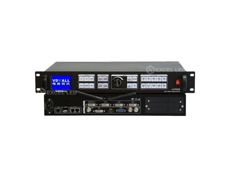
VDWall LVP909 LED Video Processor at a Glance
What is it? The LVP909 is VDWall’s LED HD video processor — the multi-output, multi-window model in the LVP family, built around four DVI output ports, 2 / 3 / 4-channel splicing and multi-window display, supplied factory-direct by Excelled Display.
What can it take in? Analog and digital mixed signals: 2×Video (PAL/NTSC), 1×VGA (RGBHV), 1×HDMI, 1×DVI and 1×SDI / HD-SDI / 3G-SDI — PC and VESA formats up to 1920×1200_60Hz for VGA and DVI, and 1920×1080p_60Hz over HDMI 1.3.
How does it reach the LED wall? Through the documented chain: the processor’s DVI OUT 1–4 ports connect to the LED sending cards (or monitors), each port driving up to 1920×1200@60Hz, while Out4 also carries a VGA preview output for current and preselect signals.
Who is it for? Integrators and AV contractors building LED walls that need mosaic splicing, mixed analog and digital sources, multi-window display and clean switching — control rooms, conference stages, studio backdrops and fixed installations.
What is included? LVP909 unit with front-panel button control and LCD status display, plus the standard accessory kit (power cord, DVI cables, RS232-RJ45 adapter cable, BNC-RCA adapters, DVI-I to VGA adapter, operation CD and user manual). An RS232 cable is available to order; configuration, datasheet and pricing from our sales team.
Four DVI Outputs and Mixed-Signal Inputs: The LVP909 Architecture
The LVP909 is defined by its output stage. Where a single-output processor pushes one canvas to one sending card, the LVP909 carries 4× DVI output ports plus 1× VGA, and every one of those DVI ports can run up to 1920×1200@60Hz or 1440×1440@60Hz. That is the hard ceiling per port, and it is the number to design your wall around.
What the four ports buy you is flexibility in how the canvas is divided. With zoom in sync, a stand-alone unit supports a maximum canvas of 14400 pixels horizontal or 6400 pixels vertical — the processor scales the source once and splits it across the ports, so a very wide or very tall LED wall is driven as a single image rather than stitched from separate players. The documented DVI output set covers both landscape and portrait shapes: 1024×768_60Hz, 1280×1024_60Hz, 1440×1440_60Hz, 1920×1080_50/60Hz, 1920×1200_60Hz, 2560×816_60Hz, 2880×800_60Hz, 3072×720_60Hz, 3600×600_60Hz, 1200×1600_60Hz and 1600×1344_60Hz.
DVI Output Ports
Out1 to Out4 on 24+5 DVI_I connectors, each capable of 1920×1200@60Hz or 1440×1440@60Hz.
Pixel Canvas
Zoom in sync lets one stand-alone unit span a maximum of 14400 pixels horizontally or 6400 vertically.
Multi-Window Ready
Single, 2, 3 or 4 image display with free size and position setup for every PIP window.
Preview Monitoring
Out4 is a DVI-I port that also carries VGA preview — monitor current and preselect signals on one screen.
Preview monitoring deserves its own note, because it is what makes the four-output layout operable in a live environment. The LVP909’s preview monitor supports monitoring current signals and preselect signals, so the operator sees what is on the wall and what is queued next before pressing Take. On the switcher application mode the unit outputs the main image on Out1 and Out2, leaves Out3 free, and dedicates Out4 to preview plus sync monitoring.

What the LVP909 Accepts: Analog and Digital Mixed Signals
The LVP909 accepts six video signals across five input connectors, deliberately mixing legacy analog with modern digital. Composite video arrives on two channels of PAL or NTSC; VGA (RGBHV) takes PC analog up to 1920×1200_60Hz under the VESA standard with R, G, B at 0.7V(p_p)/75Ω; DVI and HDMI take PC digital up to 1920×1200_60Hz, with HDMI 1.3 (CEA-861) carrying 1920×1080p_60Hz; and the SDI input handles SDI, HD-SDI and 3G-SDI in one BNC.
| Signal | Connector | Format & capability |
|---|---|---|
| Video ×2 | P4 of VGA port | Composite video, PAL / NTSC; 1V(p_p)/75Ω. |
| VGA ×1 | 15-pin D_Sub (female) | RGBHV, PC (VESA standard) ≤1920×1200_60Hz; R, G, B = 0.7V(p_p)/75Ω. |
| HDMI ×1 | HDMI type A | VESA (PC) ≤1920×1200_60Hz; HDMI 1.3 (CEA-861) ≤1920×1080p_60Hz. |
| DVI ×1 | 24+1 DVI_D | PC digital (VESA / CEA-861) ≤1920×1200_60Hz. |
| SDI ×1 | BNC / 75Ω | SDI / HD-SDI / 3G-SDI — SMPTE 259M-C, SMPTE 292M, SMPTE 274M/296M, SMPTE 424M/425M; 480i_60Hz, 576i_50Hz, 720p, 1080i, 1080p. |
| DVI OUT ×4 | 24+5 DVI_I | Out1–Out4 to LED sending cards or monitors; each port max 1920×1200@60Hz or 1440×1440@60Hz. |
| VGA preview out | 24+5 DVI_I (Out4 only) | Preview output monitors current signals and preselect signals. |
On the processing side, advanced interlaced motion image adaptive processing technology works on the incoming interlaced material to eliminate movement tails and saw-tooth artifacts — the difference between clean scrolling text on a camera feed and a visibly combed edge. Downstream, the four DVI ports hand the processed canvas to the sending cards; if that stage of the chain is new to you, the LED controller connection walkthrough covers the sending-card and receiving-card side.

2, 3 or 4-Channel Splicing with Auto-Calculated Parameters
Splicing is where the LVP909 earns its place in a large-wall design. The unit supports 2-channel, 3-channel and 4-channel splicing output, and it auto-calculates the splicing parameters rather than asking the installer to work out the maths by hand. You tell it the total width and height of the mosaic LED screen plus the size and position each output port controls; the processor then derives the matching input and output parameters for that port.
The Documented Split Modes
The vendor’s split-mode diagram documents three arrangements. Using the vendor’s own canvas labels: split mode 1 is a 1×2 mosaic labelled up to “≤4K”-wide, split mode 2 is a 1×3 mosaic labelled up to “≤8K”-wide, and split mode 3 is a vertical stacking arrangement labelled up to “≤4K”. Those labels describe the combined canvas width the mosaic can address; they are not the resolution of a single output. All four DVI outputs support 1920×1200@60Hz, and that per-port figure is what governs the sending-card plan. The configuration also supports free size and position setup of PIP images and one-key switching between different mosaic modes, with a maximal 4-unit screen mosaic for builds that outgrow a single chassis.
- Select the display mode — press the M1–M4 display mode buttons to pick the mosaic mode you are configuring.
- Select the output port — press Out1, Out2, Out3 or Out4 to choose which port’s parameters you are about to set.
- Enter the total LED screen size — the overall width and height of the finished mosaic wall.
- Describe the port’s share — set the LED screen size that this port controls and its position relative to the whole screen.
- Run Auto Calculation — the LVP909 calculates this port’s output and input parameters from those entries.
- Fine-tune and repeat — nudge the auto parameters against the actual output image if a panel-perfect seam is needed, then repeat for the remaining ports.

Auto calculation is not a shortcut around precision — it is the reason a multi-port mosaic is practical on site. Manually deriving the intercept window and output start coordinates for each of four ports invites seam errors that only show up once the wall is built; letting the processor compute them from the total screen size and per-port share keeps the geometry consistent across every port. For walls that need a different splicing toolset, the Mooncell V-series video splicer and the VX1000 all-in-one controller take other approaches to the same job.
Multi-Window and PIP: Displaying Up to Four Images at Once
The LVP909 supports single, 2, 3 or 4 image display, with free size and position setup for the PIP images rather than a fixed grid. Two application modes carry the multi-window work: AppM5 (4 image) puts any four images on the wall with Out1 and Out2 carrying the same combined output and Out4 showing output sync monitoring, while AppM6 (3 image) displays any three images with the third able to run at higher resolution as a background picture.
Because the windows are freely sized and positioned, the practical use cases are dense: a live camera feed as the background with a slide deck inset, a sponsor logo strip along the bottom, a countdown burned into a corner. PIP dual images can source from the same channel or from a different channel, so you can split one source into two windows or overlay two independent inputs, and the front panel dedicates a PIP button plus M1–M4 PIP mode keys to turning dual-picture display on and switching between its modes.

Seamless, Fade and Wipe Switching with Preselect + Take
The LVP909 gives you seamless switching, fade in fade out switching and wipe switching between any inputs, and the switching effect and time are selected from the front panel with the C/F button. Two switching workflows are documented, and they suit different operators.
One-key switching is the default: pressing an input selection button cuts straight to that source, with the switch time configured in the setup menu. Preselect + Take separates the decision from the action — you press an input button to preselect that signal, the LCD shows the preselect signal and its status once the signal is steady, and only when you press the Take button does the output move from the current input to the preselect signal. In that mode the indicator flashes quickly when the preselected source has a valid signal and very slowly when it does not, so a dead source is visible before it ever reaches the wall.
Switching also extends to the stored configurations themselves: multiple pre-stored mode calls are supported, and the transition between modes can itself run as a seamless switch or a fade in fade out switch. That is what lets an operator move from a single full-screen image to a 3-channel mosaic mid-event without a blank frame.

The LCD status screen reports the working state throughout: current input and its format, preselect input and its status, output position and size, switch mode, switch time and the active application mode. Our LED video splicer guide covers how switching behaviour differs across splicer and processor classes if you are still choosing a category.
Wiring, Control and Cascade: Configuring the LVP909
The LVP909 is a 1U 19-inch rack chassis measuring 483 (L) × 274 (W) × 66.6 (H) mm, drawing ≤45W from a 100-240VAC 50/60Hz supply. The wiring sequence below follows the documented hardware connections, from rack mount through to the sending cards.
- Rack and power the unit — 1U of a standard 19-inch rack, 100-240VAC 50/60Hz, rated ≤45W.
- Connect the sources — composite video to the video port (V1/V2, on P4 of the VGA port) using the supplied BNC-RCA adapters; VGA to the 15-pin D_Sub; HDMI to the type A port; DVI to the 24+1 DVI_D port; SDI / HD-SDI / 3G-SDI to the BNC input.
- Connect the LED sending cards to Out1–Out4 — 24+5 DVI_I connectors, each port configured within its 1920×1200@60Hz or 1440×1440@60Hz ceiling.
- Connect the preview monitor — Out4 is a DVI-I port that also carries VGA output, so a single screen can show the current signal and the preselect signal side by side.
- Choose the application mode — AppM1 switcher, AppM2 / AppM3 / AppM4 for 2, 3 and 4-channel mosaics, AppM5 (4 image) or AppM6 (3 image) for multi-window work.
- Set the mosaic geometry — enter total LED screen width and height, each port’s controlled screen size and position, then run Auto Calculation and fine-tune items 2.9–2.16 against the real output.
- Confirm and let the unit restart — in the Output CFG menu, select item 1.3 Setup and press OK, then confirm the prompt; the system restarts and the changed parameters take effect.
- Set switching behaviour — choose the switching effect and time, then select one-key switching or Preselect + Take for the operator.
- Save and secure — store the mode for recall, and use the Lock button to freeze the panel once commissioning is done.
Control Methods: Panel, RS232, USB, LAN and WiFi
Everyday operation runs from the front panel buttons with the LCD status display: input selection keys (V1, V2, VGA, DVI, HDMI, SDI), output port keys (Out1–Out4) for mosaic modes, image keys (IMG1–IMG4) for multi-window modes, the C/F switching-effect key, Take, PIP, Brightness +/−, VGA Auto adjustment, Info and Lock. Beyond the panel, control is available over RS232, USB and LAN, with a WiFi control interface on the unit, so a show can be driven from a PC or a tablet.
Cascade: One PC, Multiple Units
The rear panel carries RS232 IN and RS232 LOOP. The RS232 IN port connects a PC for software control; the RS232 LOOP port cascades to the RS232 IN of the next LVP909 unit, so a single PC can control every processor in a rack. Combined with the supported 4-unit screen mosaic, that is the documented path to canvases that exceed one chassis — additional units extend the wall while the control surface stays a single seat.

VDWall LVP909 vs LVP615S vs LVP605: Which One Fits?
Three VDWall processors, three different balances of inputs, outputs and power. The specs below are taken from the published VDWall documentation for each model.
| Model | LVP909 ☆ | LVP615S | LVP605 |
|---|---|---|---|
| Video inputs | 2×Video, 1×VGA, 1×HDMI, 1×DVI, 1×SDI | 2×Video, 1×YPbPr, 2×VGA, 1×DP, 1×DVI, 1×HDMI, 1×SDI + SDI loop | 3×Video, 1×S-Video, 1×YPbPr, 2×VGA, 1×HDMI, 1×DVI, 1×EXT |
| Outputs | 1×VGA, 4×DVI | 1×VGA, 2×DVI | 1×VGA, 2×DVI |
| Output resolution ceiling | 1920×1200@60Hz or 1440×1440@60Hz per port | Custom output width ≤3840, height ≤1920 | Custom output max horizontal 3840 or vertical 1920 |
| Splicing | 2 / 3 / 4 channels, auto-calculated | — | — |
| Multi-window | Single, 2, 3 or 4 images with PIP | — | — |
| Image processing | Interlaced motion adaptive processing | Faroudja Real Color / DCDI / TrueLife | — |
| Power consumption | ≤45W | ≤25W | ≤20W |
| Typical fit | Multi-output splicing and multi-window walls | SDI-loop builds with projector-grade processing | Compact legacy-source control rooms |
Read the table by output count first. If your wall plan needs more than two channels of splicing, or four images on screen at once, the LVP909 is the only one of the three with the output ports to do it. If the build is a straightforward single or dual-screen install with an SDI loop for a confidence monitor, the LVP615S carries the extra input variety including YPbPr, DisplayPort and a second VGA. Where a small legacy-source rack with S-Video, EXT and three composite inputs is the requirement, the LVP605 fits the bill at the lowest power draw of the three.
Model pages: VDWall LVP615S LED HD video processor · VDWall LVP605 LED video processor · VDWall LVP100 compact LED video processor. Send the wall dimensions and source list and our engineers map the chain, the sending-card plan and the quote in one reply.
VDWall LVP909 Technical Specifications
| Parameter | Specification |
|---|---|
| Product type | LED HD video processor with multi-output splicing and multi-window display |
| Inputs (type / number) | 2×Video; 1×VGA (RGBHV); 1×HDMI (VESA / CEA-861); 1×DVI (VESA / CEA-861); 1×SDI (SDI / HD-SDI / 3G-SDI) |
| Video system | PAL / NTSC |
| Composite video level | 1V(p_p) / 75Ω |
| VGA format | PC (VESA standard) ≤1920×1200_60Hz; R, G, B = 0.7V(p_p) / 75Ω |
| DVI / HDMI format | PC (VESA standard) ≤1920×1200_60Hz; HDMI 1.3 (CEA-861) ≤1920×1080p_60Hz |
| SDI format | SMPTE 259M-C, SMPTE 292M, SMPTE 274M / 296M, SMPTE 424M / 425M; 480i_60Hz, 576i_50Hz, 720p, 1080i, 1080p |
| Input ports | Video: P4 of VGA port; VGA: 15-pin D_Sub (female); HDMI: type A; DVI: 24+1 DVI_D; SDI: BNC / 75Ω |
| Outputs (type / number) | 1×VGA, 4×DVI |
| Preview output | 1×VGA (DVI OUT4) — monitors current signals and preselect signals |
| DVI output formats | 1024×768_60Hz; 1280×1024_60Hz; 1440×1440_60Hz; 1920×1080_50/60Hz; 1920×1200_60Hz; 2560×816_60Hz; 2880×800_60Hz; 3072×720_60Hz; 3600×600_60Hz; 1200×1600_60Hz; 1600×1344_60Hz |
| Output connectors | DVI OUT: 24+5 DVI_I; VGA OUT: 24+5 DVI_I (Out4 only) |
| Per-port output ceiling | Each output port max 1920×1200@60Hz or 1440×1440@60Hz |
| Maximum canvas | Zoom in sync — stand-alone unit supports maximum 14400 pixels horizontal or 6400 pixels vertical |
| Splicing output | 2-channel, 3-channel and 4-channel splicing; auto-calculates the splicing parameters; maximal 4-unit screen mosaic |
| Multi-window | Single, 2, 3 or 4 image display; free size and position setup of PIP images; PIP dual images can source from the same or a different channel; one-key switch of mosaic modes |
| Switching | Seamless switching, fade in fade out switching and wipe switching between any inputs; one-key switching and Preselect + Take switching; multiple pre-stored mode calls with seamless or fade transitions between modes |
| Image processing | Advanced interlaced motion image adaptive processing technology to eliminate video image movement tail and saw-tooth phenomenon |
| Control ports | Panel / RS232 / USB / LAN / WiFi; RS232 IN plus RS232 LOOP for cascading control of multiple units from one PC |
| Input voltage | 100-240VAC 50/60Hz |
| Power consumption | ≤45W |
| Environment | Temperature 0-45°C; humidity 15-85% |
| Dimensions | 483 (L) × 274 (W) × 66.6 (H) mm — 1U 19-inch rack form factor |
| Weight | G.W. 5.5 kg / N.W. 4.2 kg |
| Optional accessory | RS232 cable available to order |
Documentation note: marketing material outside the datasheet sometimes labels this class of processor “4K”. The verified figures in the table above are the ones to design to — a maximum of 1920×1200@60Hz or 1440×1440@60Hz on each output port, and a 14400 × 6400 pixel maximum canvas across ports when zooming in sync.
VDWall LVP909 Manual, Datasheet and Control Software
Two official VDWall documents sit behind everything on this page, and both are worth having before you specify the unit. The “Overview of LVP909” (V1.2) is the short form: the feature list and the specification table covering inputs, outputs, formats, connectors, power, environment, dimensions and weight. The “LVP909 User Manual” is the working document: the item list and standard accessories, the rear-panel port descriptions, the front-panel button reference, the six application modes with their signal-routing diagrams, the basic user instructions for signal switching, and the full setup menu reference.
If you need either document, request the LVP909 datasheet and manual through our sales team — we send the vendor PDFs together with the quote for your configuration, so the specification you design to is the specification that ships.
What the Manual Covers in Detail
The user manual walks the whole commissioning path rather than just the spec sheet. It opens with the six application modes — AppM1 (switcher), AppM2 (2 mosaic), AppM3 (3 mosaic), AppM4 (4 mosaic), AppM5 (4 image) and AppM6 (3 image) — each with its own signal-routing diagram showing exactly which output ports are live in that mode. From there it documents the four setup menu sections you will actually use on site: 1. Output CFG (output resolution and application mode), 2. Output Image (the mosaic parameter table including Auto Calculation), 3. Image Source, 4. Color & Brightness (brightness, contrast and colour, each 0–100 with a default of 50), 5. Communication (IP, mask, gateway, MAC and Device ID), 6. Language (Chinese and English) and 8. Advance. The manual also carries the RS232 cable order drawing, which matters because that cable is an order-time item rather than a stock accessory.
Control Software: PC Program, Device ID and Multi-Unit Addressing
Day-to-day control is split between the front panel and the network. The LVP909 is listed as a Panel / RS232 / USB / LAN / WiFi controlled unit, and the manual documents a PC control program that reaches the processor either through the rear RS232 IN port or over Ethernet. What makes multi-unit racks manageable is the Communication menu (section 5): alongside IP address, subnet mask, gateway and MAC it exposes a Device (ID) field, which exists to number the multiple LVP909 units sitting under the same IP — so one PC can address each processor in the rack individually instead of having to be re-plugged. Combined with the RS232 IN / RS232 LOOP pair, that gives you both network addressing and a serial chain for the same rack.
Commissioning behaviour is documented too: changes made in the Output CFG menu are applied through item 1.3 Setup, and the unit prompts you to restart before the new parameters take effect — a step worth knowing before you conclude that a setting “did not work”. If you would rather have us walk the configuration for your wall, send the wall size and source list to our engineers and we will map the application mode, port assignment and cabling on paper before you build.
VDWall LVP909 LED Video Processor FAQ
Q1 What is the VDWall LVP909 LED video processor?
The LVP909 is VDWall’s LED HD video processor and the multi-output, multi-window model in the LVP family. It is built around four DVI output ports plus a VGA output, supports 2, 3 and 4-channel splicing with automatic parameter calculation, and displays single, 2, 3 or 4 images with free PIP sizing.
Q2 What inputs does the LVP909 accept?
Six video signals across five connectors: 2×Video (composite PAL/NTSC, 1V p_p into 75Ω), 1×VGA (RGBHV, 15-pin D_Sub female), 1×HDMI (type A), 1×DVI (24+1 DVI_D) and 1×SDI (BNC, 75Ω) covering SDI, HD-SDI and 3G-SDI.
Q3 What are the LVP909’s outputs and maximum output resolution?
Outputs are 1×VGA and 4×DVI on 24+5 DVI_I connectors. Each output port supports a maximum of 1920×1200@60Hz or 1440×1440@60Hz. Documented DVI output formats include 1024×768, 1280×1024, 1440×1440, 1920×1080_50/60Hz, 1920×1200, 2560×816, 2880×800, 3072×720, 3600×600, 1200×1600 and 1600×1344, all at 60Hz unless noted.
Q4 Is the LVP909 a 4K input or 4K output processor?
No. The verified output ceiling is 1920×1200@60Hz or 1440×1440@60Hz on each output port, and the maximum input formats are 1920×1200_60Hz on VGA and DVI with 1920×1080p_60Hz over HDMI 1.3. Descriptions of this unit as a “4K” processor do not match the datasheet; plan your sending-card layout around the per-port limit and the four-port canvas instead.
Q5 What is the maximum canvas the LVP909 can drive?
With zoom in sync, a stand-alone unit supports a maximum of 14400 pixels horizontal or 6400 pixels vertical. That is the total canvas addressed across the output ports, not the resolution of any single port — each port still tops out at 1920×1200@60Hz, which is why large walls are split into multiple channels.
Q6 How does the LVP909’s splicing auto-calculation work?
Select the display mode with the M1–M4 buttons, select an output port with the Out1–Out4 buttons, then enter the total LED screen width and height plus the screen size and position that port controls. Running Auto Calculation makes the processor derive that port’s output and input parameters automatically. Use it rather than hand-entering the intercept and start coordinates: manual entry across four ports is the usual source of seam misalignment, and the calculated values can still be fine-tuned against the real output afterwards.
Q7 Can the LVP909 display multiple windows or PIP?
Yes. The unit supports single, 2, 3 or 4 image display with free size and position setup of the PIP images. Two application modes handle multi-window work: AppM5 (4 image) and AppM6 (3 image). PIP dual images can source from the same channel or a different channel, and mosaic modes can be switched with one key.
Q8 What switching effects does the LVP909 support?
Seamless switching, fade in fade out switching and wipe switching between any inputs. Switching effects and time are selected with the C/F button. Two switch workflows are available: one-key switching, which is the default, and Preselect + Take, where you preselect a source and then press the Take button to move the output to it.
Q9 How many units can be cascaded for a larger wall?
The rear panel provides RS232 IN and RS232 LOOP. RS232 IN connects a PC for software control, while RS232 LOOP feeds the RS232 IN of the next unit so a single PC can control every processor in the rack. The LVP909 also supports a maximal 4-unit screen mosaic for walls that exceed one chassis.
Q10 How is the LVP909 controlled on site, and does it need PC software?
It does not need software to run — the front panel buttons with the LCD status display cover input keys (V1/V2/VGA/DVI/HDMI/SDI), output keys (Out1–Out4), image keys (IMG1–IMG4), C/F, Take, PIP, Brightness, VGA Auto, Info and Lock. Beyond that, control is available over RS232, USB, LAN and WiFi, and VDWall documents a PC control program that connects via the RS232 IN port or over Ethernet. The Communication menu exposes IP, mask, gateway, MAC and a Device (ID) field used to number multiple LVP909 units under the same IP so one PC can address each processor in the rack.
Q11 There is no signal on one of the four DVI outputs — what should I check?
Check the application mode first, because some ports are deliberately inactive in certain modes: in AppM1 (switcher) Out1 and Out2 carry the main output, Out3 has no output and Out4 runs preview plus sync monitoring, and in AppM5 (4 image) Out3 likewise has no output. If the port should be live, confirm the Output CFG menu is applied — resolution and application mode changes go through item 1.3 Setup and press OK, after which the unit restarts before the new parameters take effect. Then verify the port’s mosaic parameters were generated by Auto Calculation and that the source itself is valid.
Q12 How do I check a signal before it reaches the wall, and where can I get the manual or buy an LVP909?
Use the preview monitor: Out4 is a DVI-I port that also carries VGA output, and the preview output monitors both current signals and preselect signals, so you can confirm a source and see what is queued before pressing Take. In Preselect + Take mode the LCD reports the preselect signal and its status once the signal is steady, and the indicator flashes quickly for a valid signal and very slowly when there is none. For the manual, we supply the official VDWall “Overview of LVP909” and “LVP909 User Manual” documents with your quote. On availability and price, the LVP909 is supplied factory-direct and quoted per configuration — send your wall size, source list, sending-card model and quantity and we will confirm stock, configuration and pricing in one reply.
The VDWall LVP909, Delivered as a Four-Port Splicing Front End
VDWall LVP909 gives integrators one 1U processor that takes mixed analog and digital sources, splices them across up to four DVI output channels with auto-calculated parameters, and displays up to four images with free PIP placement — backed by Excelled’s pre-shipment testing and factory-direct support. Pair it with our LED sending and receiving hardware for a complete control chain.
Related reading: LED control system · DH7516 LED receiving card · Novastar vs Colorlight vs Linsn · Request a quote